The FINAL Blog Entry: Project Development
In this blog, I will:
1. Briefly describe my team chemical device
2. Show how the team planned, allocated the tasks, and executed the project.
3. Document the entire design and build process of the chemical device and
include videos, pictures, and screen captures of the processes.
4. Include “Hero shot” of every milestone of the processes, example the part A
that was 3D printed, part B that was laser-cut, electronics components
moved/worked according to the program. Hero-shot is taken with the person-
in-charge holding/working/making the parts.
5. Include the name of the person who was in-charge of every part of the project.
6. Document my individual contribution to this project.
7. Provide the link to the page of the blog of my teammates.
8. Describe problems encountered and how the team solved them.
9. Include all the project design files as downloadable files.
10. Embed the final prototype design file, i.e., the final fusion360 design file
showing the entire prototype.
11. Type my Learning reflection on the overall project development.
1. Our team Chemical Device
So... What is the chemical device that my team has decided to embark on? Well we decided to create a device that can read and the displace the amount of CO in the environment based on the concentration. I will go into further detail with as we move on.
The objective of our product is to prevent Carbon Monoxide related incidents such as CO Poisoning and asphyxiation. With this detection and removal system, such incidents will be mitigated and many lives would be saved.
In this day and age of the growth and development of the world, the construction and fabrication of materials and parts are very common. Many parts in buildings and other projects require welding, soldering, melting, and burning of materials. With burning comes combustion whereby oxygen, mixed with fuel, will produce carbon dioxide. Carbon Dioxide is relatively harmless but combustion will inherently always produce Carbon Monoxide which is due to incomplete combustion. Carbon Monoxide can also be produced during cooking. This harmful gas binds to the red blood cells and hinders their oxygen intake which will cause oxygen deprivation. In most cases, CO poisoning will cause nausea, dizziness, and vomiting among other things but in serious cases, it can cause death.
Our Carbon Monoxide (CO) Detection and Removal System(CODRS) is a device that would be placed at or around confined spaces where a lot of welding will be taking place.
The subsequent photos are the final design sketches of our chemical device.


The sketch on the left is a see through sketch of the internal components of the chemical device. The animation sketch on the right is basically what the device will look like when it is complete.
As seen on the left, the chemical device has 'vent holes' on the base and the adjacent back piece. This is too allow the air with the CO to flow into the device. The MQ2 CO sensor is protruding from the base of the device which will subsequently activate the fan once the concentration of CO starts to approach lethal levels then the fan will blow the the air with the CO away.
As seen on the right, hole to allow the CO to flow would need to be opened by turning the gear. The gear mechanism is put in place in any case welding not being one for a prolonged amount of time. It will help decrease the dust build up in the device but in most cases it will be open.
So our chemical device will placed above welding stations and blow out the CO into either an exhaust system or outside of the room. An exhaust system would be ideal as we would not want to cause more air pollution with the CO.

.jpeg)
Above are more sketches of the front and side view for better angles of where all the components are placed.
As mentioned previously, the CO sensor is placed at the bottom as the air would mostly be rising upwards into the box. Additionally, along with the fan being activated, the LED will also flash to also alert the user to either leave the area for a while or stop welding for a while until the LED stops flashing.
2. Team Planning, Allocation and Execution
This is the task allocation of the group,

The chart quite self-explanatory. Clive (CSO) and Joelle (CFO) were tasked to do things related to 3D printing and laser cutting while Adyl (COO) and I (CEO) did the Arduino programming and I also provided the base designs for the CAD with all the sketches.

Above is the finalized Bill of Materials (BOM). We initially wanted a motor before we found out the motor the Arduino kit provided was enough. We also had to swap the CO sensor from MQ7 to MQ2, and we also added arcylic as we decided to laser cut as well.

Above is the finalized Gantt chart. I would say for the most part we did try to follow it as closely as possible to avoid last minute work but some days it was difficult to muster the 'strength' to really do anything because we were also preparing for our CP5098 paper and elective papers. I would say that we finished at a comfortable time though. We has a lot of time to troubleshoot and put together everything, as you will see further on into the blog.
3. Design and Build Process
Part 1. Design and Build of Base and Gear (+ Rods) done by Clive and me
For the most part a lot of my contribution for this project was on the designing end and I did help advice on the building end when there needed to be troubleshooting updates to the design.
The group realised on the first day of 3D printing, that we needed to have a mechanism in place for the chemical device so I came up with something that could be done with gears that the group decided to implement.

The above... um... sketch? LOL- That was where the idea sprang out from. I drew it on the whatsapp drawing feature just as an initial proposal to the group and, yes we all agreed to do this. So, I then made a more detailed drawing as seen below and the animation on how it will work which I will insert again below.


Yes so the left is the still image while the right is the, again, animation to show the mechanism. Below I will show the design process of the sketches.


Above I also inserted the CAD animation done by Joelle. For the rest of the building of part 1, you can look at Clive's blog. Here is the final gear component printed out by Clive and a photo of me and the sketches.
Link to Clive's blog: CLIVERINO


Part 2. Design and laser cutting of walls and 3D printing of motor house done by Joelle and me
Again, I contributed mostly in the design of this.
After going through the idea refinement and consulting with Dr Noel, the group had to rethink the initial design of the product. Below was the initial sketch of our final design.

Because of the TRIZ we designed it so that there are 4 smaller fans instead of one bigger fan in the actual product but for the purposes of the the prototype we only used one fan. It did give Joelle a sigh of relief when we were discussing as printing extra components would be very mafan lol.

Above is the final design of the motor house. It was planned to be glued onto the inner side of the chemical device that did not have any vents as we wanted to prevent any disruption air flow. This was due to the changing of concept idea by putting vents at the base and back of the device as seen below.

The above sketch is the finalized design of the chemical device and is what Joelle based the 3D print and laser cutting off of. The design also consisted of the tab and slot, which was Joelle's idea, that would allow the walls, base, and 'ceiling' to be all connected together. You can see the tabs and slots in the base and upper part of the sketch.
Below is the process of drawing all these sketches.


For the rest of this building process, I will provide the link to Joelle's blog for her part. Below is also a photo of the final laser cut put together after she cut.
Link to Joelle's blog: JOEEEEEEEEELLLEEEEEEEEEEEEEEEEEE
.jpeg)
Part 3. Coding of Electronics done by Adyl and me
For the coding, the idea was to code the motor to be spinning when the entire system is turned on and LED to flash once the CO approaches lethal levels. I tried to program the motor to already spinning with the push of the button. This was to simulate that once someone wants to start welding, he/she will just have to turn on the device and the fan will begin to spin. The initial plan for this was that Adyl program the LED and me the motor. However, I was not able to figure out how to get the motor to run, neither did Adyl so we switched to a servo to simulate the motor and fan.
The initial code of the servo was the standard servo swing code but set to a really high loop value and the normal wiring done by Adyl. The servo code did have a problem which I fixed (will be explained in the later section). So Adyl and I were able to get the servo swing for what seemed like an 'infinite' loop so it can last for the whole welding session but after consulting with Dr Noel, we realised that the Arduino kit had a transistor so we changed the whole entire thing to cater for the motor programming. Adyl did the bulk of this as I did not know much of how to code the motor.
This was the code we used:
#define Sensor_Pin A0
#define Digital_Pin 2
void setup() {
// put your setup code here, to run once:
Serial.begin(9600);
pinMode(2, INPUT_PULLUP);
pinMode(5, OUTPUT);
pinMode(12,OUTPUT);
pinMode(9,OUTPUT);
}
void loop() {
// put your main code here, to run repeatedly:
Serial.println(analogRead(Sensor_Pin));
delay(1);
Serial.println(digitalRead(Digital_Pin));
delay(1);
int sensorVal = analogRead(Sensor_Pin);
if (sensorVal >=5166)
{
digitalWrite(12, HIGH);
digitalWrite (5, HIGH);
delay(100);
digitalWrite(5, LOW);
delay(100);
}
else (sensorVal <<5166);
{digitalWrite(5,LOW);
digitalWrite(12,LOW);}
}
When it came to this code, there was some calibration that needed to be done as when we checked the the sensor values in the serial monitor, if it was reading in ppm then the whole room would have extremely high levels of CO as it said there was about 370ppm of CO... Sustained levels of CO at 70ppm would be enough to cause noticeable effects already so I just did some calibration.
At the serial monitor of 370 we associated this value with the average concentration of in the environment of about 5ppm. Then I scaled it accordingly to what the serial monitor would read if 70ppm was reached. Thus, at around 5ppm the serial monitor would 370 and at 70ppm it would read about 5166. So the code states that the fan and LED will turn on once 5166 is reached. This is an acceptable value as 70ppm would need to be maintained in the air for a few minutes before any effects are noticed. Putting the device to work at the lower limit allows the user enough time to react to the LED and even if they do not react in time, the fan can displace the CO before it accumulate.
Here's the link to Adyl's blog: AAAAAAAAADYLLLLLLLLL
Below is the code and hardware all together without the main body yet.


.jpeg)
Part 5. Integration of All Parts and Electronics done by everyone :O
For the first part of the integration, Clive and Adyl assembled the all the different parts of the 3D print and laser cut. They used acrylic glue as the structure was not as stable when all electronic components are placed inside. You can refer to Adyl's blog for the process of the gluing.
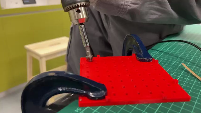
Then we drilled a hole into the base of the device to allow for the CO sensor to protrude out and another hole for the power cord to the Arduino. Below is the video of me drilling it.
Next Adyl also welded the wires together so that the internals of the chemical device would be a lot neater, as seen below.

Putting all the parts together was relatively simple, everyone was there to do their part. Referring the photos below.


.jpeg)
It would be quite hard to pin point who did what on that final day for assembly as everyone contributed to the integration of everything. It was just kind of like we all knew what needed to be done and we all were just in-sync and kind of passed around the device to get things done. The hole for the CO sensor kept getting wet for some reason...
Below you can look around our CAD design of the chemical device.

Below is the video of the simulations of the chemical device.
The first video is an example of the calibration. The LED and fan will only activate once the CO levels approach lethal, which the serial monitor knows as 5166. Since we do not have any CO available, we just dropped the level in the arduino to simulate that the CO concentration has increased.
The second video is a reenactment of what it would look like if the chemical device was used.


So yes this is our final product!

.jpeg)


4. Problems and Solutions
Problem 1: Printing the box takes too long
Solution 1: sized it to be smaller
Problem 2: 3D printing the walls take too long and is not practical because only left 1.5 weeks till deadline
Solution 2: Changed the 3D printing of walls to laser cutting the walls
Problem 3: There was no opening to stick the Gas sensor and arduino wire through the box
Solution 3: Drill HOOOOLLLEEEE
Problem 4: Initial servo code made the back and forth swinging of the servo too inconsistent to act as a fan
Solution 4: Reviewed code with previous iterations of code done in practicals and practises and edited the code accordingly
Problem 5: When using the servo, the arduino could not be programmed to run the servo swing and the LED
simultaneously. the servo would only operate despite the LED’s code being uploaded as well.
Solution 5: We looked through the arduino kit and realised that there is a transistor, after consulting Dr Noel, and just changed the servo into the intended moto
5. Project Design Files as Downloadable Files
You can access all the files we have used with this link: YAY
6. My Learning Reflection
I think I would say that this whole process of project development was a very tedious process as compared to ICPD as the things we designed had to be mostly 3D printed or laser cut and not just cardboard along with the coding. Honestly, when I saw all the examples at the start of semester 1 on the first few lessons of ICPD, I couldn't imagine myself having to have done any 3D printing, laser cutting or coding or even designing something using sketching but hey I'm at the end of CPDD and did all that so I guess there is some pride in having survived all that lol.
Personally, I would say that the planning and design stage was the most stressful, especially when it came to the idea refinement. I think when it came to the TRIZ we did have quite a bit of difficulty figuring out what to do. At the time as well, we tried to put together the idea refinement report while all of us were on holiday, scattered around the world. I remember Clive joining in on the voice call. He turned on his video and he was in full winter wear standing in the middle of snow. It was quite funny. These are just some examples of the stresses we experienced. I think arriving to what our final product should look like, getting to our final design sketch, was more difficult than actually making the chemical device. There was just so much planning that needed to be done and so much more details that needed to be fixed which is why the group is thankful to Dr Noel and the rest of the lecturers for giving us the opportunity to refine our idea refinement. Looking back on our first draft of the idea refinement, it was quite a bad design LOL. Just like the previous assignment in ICPD things progressively got easier from the start to finish of this project.
With all the problems one faces, there is always things to learn. I definitely learned from this whole thing. The Gantt chart and the flow of the tasks was one thing I will definitely use in the future. The Bill or Materials is also another thing that was new to me.
I think one of the biggest things in when it comes to these kind of 'situations' is to really just keep moving forward. If you don't fight, you lose. If you fight, you win. Fight. Fight.
Despite all the problems faced, there were definitely some good memories we made along the way and actually looking back on the whole process to see how the product was just an idea in our heads and now it is sitting right in front of us, it is quite fulfilling to me, I don't know about the rest haha.
LASTLY, just want to say that I am extremely grateful and thankful to this group that I had to work with. Due to... some circumstances last semester for the assignment similar to this one, I cannot imagine myself having to go through this assignment in those similar situations. This is why I cannot emphasize enough how much I am thankful for this team to be able to rely on them for the different tasks we all had. Shoutout to Adyl, Clive and Joelle.